Basic Element that helps to analyze any Electronic Circuit – The Schematic Diagram

Basic Element that helps to analyze any Electronic Circuit – The Schematic Diagram

If you are beginner to know all about schematics then this blog will be your helping guide to understand how to read, build, and simulate the schematics with user-friendly tools. Make sure that you read till the end. One of the most essential skills for an electrical engineer is the ability to read and create schematics.


Before you start learning Ohm’s law, superposition theorem, and delta-wye transforms, you need a basic understanding of how to read (and draw) a circuit schematic.

Why Schematic is called a basic element of Circuit diagram?

Many times you have got a chance to see an electrical circuit board with more symbols than any information and understanding of those symbols is one of the must skill for any electrical engineer. Before exploring about the circuit diagrams, let us see what schematic diagram is:


“A schematic diagram is nothing but the representation of all the elements or components of a system or an electrical circuit with the help of schematic symbols along with their interconnections. It is an industry standard to represent all the physical components of a circuit”

How to read a schematic?

Every new electrical circuit board design starts as an idea. That idea is then defined, with words and diagrams, in a specification. Anyone can take an idea this far, but the next step requires a fundamental understanding of circuit schematics.

Circuit schematics are the bridge between conceptual electrical design and physical realization of a printed circuit board assembly, or PCBA.


Schematics have two fundamental purposes. First, they communicate design intent. To someone skilled in the art of electrical design, schematics should clearly convey the intent of the design. And second, they exist to direct and drive the PCB layout.


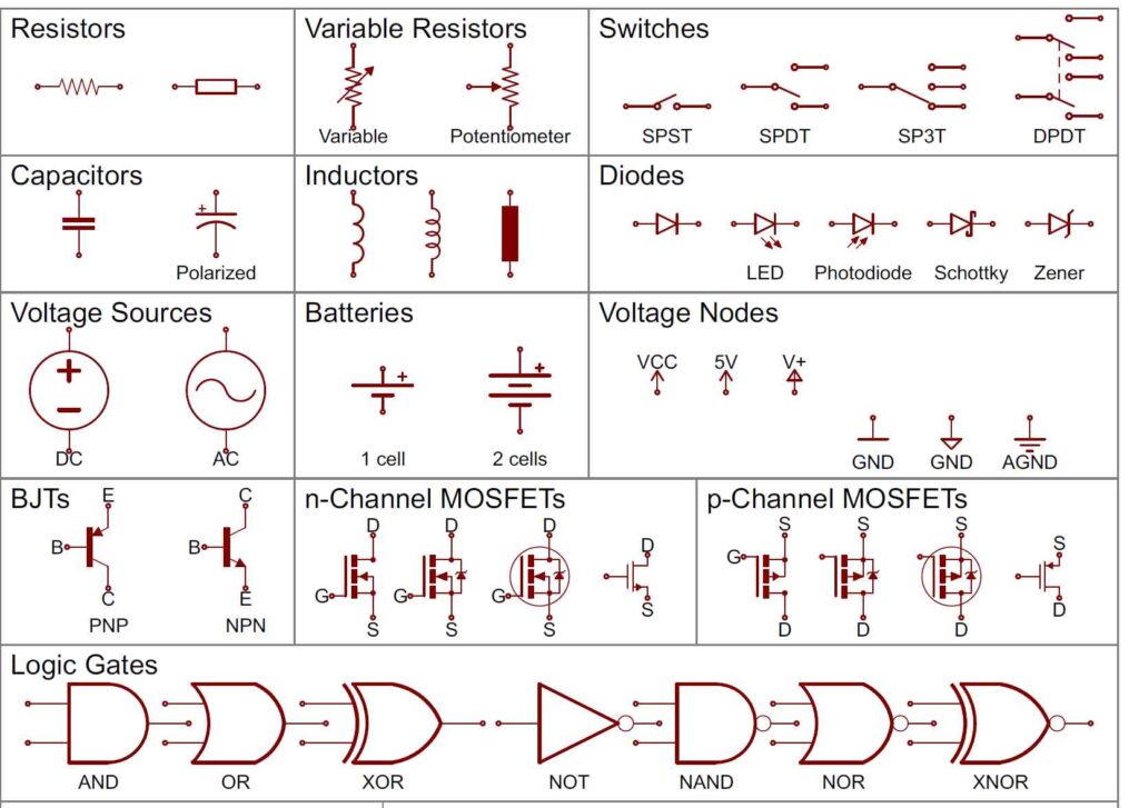
To get a good start on understanding schematics you should understand some basic things: component symbols, reference designators (REFDES), nets, and outputs.


The first step is to identify the basic schematic symbols of all the electrical components such as resistor, capacitor, inductor, potentiometers, switches, power sources, diodes, Op-amp, transistors and so on.

If you encounter an integrated circuit it includes a rectangular box where each pin is numbered and labelled. In this case the user should be familiar with the function of each pin.

The next step is to analyze the circuit with the help of nets, nodes and junctions which are represented with unique colors in some circuits. From this we can know how the terminals are connected and in different directions within the circuit.


Finally, if it is a complex circuit then follow the divide and rule formula by splitting the functional blocks separately and then analyze each block by using the above mentioned steps. 

Interesting and ease-of-use tools for building schematic:

Once you are familiar with the schematic diagram, now it’s your turn to illustrate them with the help of software tools. We will look into a few interesting and user-friendly tools one by one.

Schematic tools for Simulation - Next step towards getting your circuit ready

After building the circuit, the next step is to simulate it to check whether it’s giving the required output or not.  

LTSpice is one of the most popular and widely used tool for SPICE simulation. It is a free-circuit simulation tool. The user should be accurate about the circuit such as input signals, supplies, simulation type etc.

It is a good performer to draw and simulate the analog circuits rather than mixed signal or digital circuits. NgSpice, GnuCap, EasyEDA, CircuitLogix are some of the other popular tools used for schematic simulation.

Bottom Line


Schematic diagrams are essential to know how the components are interconnected, how the signal flows through the circuit, what voltage should appear at which node and so on. If we want to deal with any broken electronic device then having a schematic saves both time and money.


So far we have discussed about how to read a schematic and what are the different tools used to build and simulate it. We have to select an appropriate tool depending upon the type of schematic we are drawing.

Recently Published

Popular Newsletters

Most Viewed

Trending

Start your next project with us